
CNC Turning vs Milling,What are the Differences?
In the field of mechanical machining,Turning vs Milling are two of the most fundamental and widely used cutting processes. Their core differences stem from the fundamental distinctions in processing principles, motion forms, and applicable scenarios, which can be specifically distinguished across the following six key dimensions:
I. Core Machining Principle: The Fundamental Difference of "Who Moves and Who Stays Still"
This is the most essential difference between turning and milling, directly determining their respective machining logic:

- The workpiece rotates, while the tool remains fixed (or only performs linear feed). During machining, the workpiece is clamped on the machine spindle and rotates at high speed with the spindle (this is the “primary motion,” providing the cutting power).
- The turning tool is fixed on the tool post and only moves slowly in a straight line along the axis or radially of the workpiece (this is the “feed motion,” controlling the cutting amount). The excess material on the workpiece surface is removed by the tool edge, forming a rotational surface.
- Analogy: Similar to “peeling an apple”—the apple (workpiece) rotates, while the fruit knife (turning tool) remains fixed or moves slowly, peeling off the circular skin of the apple.
- The tool rotates, while the workpiece remains fixed (or performs feed motion). During machining, the milling cutter (a multi-blade tool) is clamped on the machine spindle and rotates at high speed with the spindle (primary motion).
- The workpiece is clamped on the worktable and moves linearly or along a curve along the X/Y/Z axes (feed motion). The multiple cutting edges of the milling cutter alternately cut the workpiece, forming planes, grooves, complex contours, and other non-rotational surfaces.
- Analogy: Similar to “grinding a tabletop with a grinding wheel”—the grinding wheel (milling cutter) rotates, while the tabletop (workpiece) moves slowly, grinding out a flat surface.
II. Applicable Machining Objects: "Rotational Parts" vs. "Non-Rotational Parts"
The machining principles of the two determine significant differences in the shapes of parts they are suitable for:
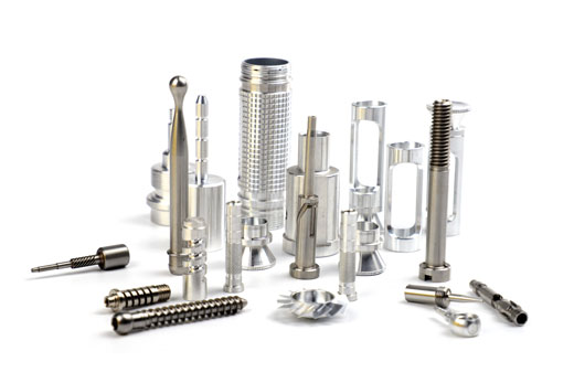
- Rotational parts (i.e., parts whose contour shape remains unchanged when rotated around a certain axis).
- Common workpieces include bar-shaped cylindrical parts, such as shafts (e.g., motor shafts, stepped shafts), discs (e.g., flanges, gear blanks), sleeves (e.g., bearing sleeves, hydraulic cylinder barrels), and threads (e.g., bolts, nuts).
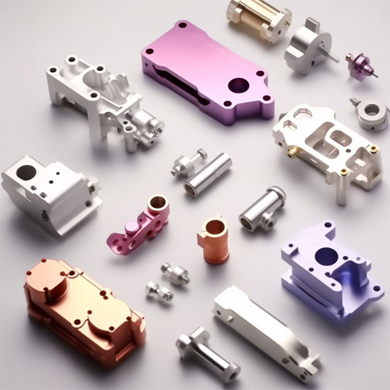
- Non-rotational parts (or non-rotational features on rotational parts).
- Common workpieces include rectangular or irregularly shaped parts, such as housing parts (e.g., gearbox housings), support parts (e.g., machine tool supports), flat surfaces (e.g., steel plate surfaces), grooves (e.g., V-grooves, T-grooves), and complex contours (e.g., mold cavities, turbine blades).

- Simple structure, mostly single-blade tools (a few special turning tools are multi-blade, such as forming turning tools). The blade shape is designed according to machining requirements (e.g., external turning tools, internal turning tools, cutoff tools, thread turning tools).
- Characteristics: Easy to manufacture and grind, low cost; but single-blade cutting means only one blade works at a time, resulting in relatively lower machining efficiency (suitable for continuous cutting of rotational surfaces).
- Complex structure, mostly multi-blade tools (blade count ranges from 2 to dozens). Common types include:
- End Mill: Used for machining planes and step surfaces.
- Ball Nose Mill / Square End Mill: Used for machining grooves, side surfaces, and complex contours.
- Three-Flute Mill: Used for machining straight grooves.
- Forming Mill: Used for machining specific-shaped contours (e.g., gear tooth slots).
- Characteristics: Multi-blade alternating cutting results in high cutting efficiency (especially in high-speed milling); but the tool requires high manufacturing precision and has a higher cost.

IV. Machining Motion Form: "Single Feed" vs. "Multi-Axis Compound"
- The combination of primary and feed motions differs between the two, determining the flexibility of machining:
- Turning Motion: The motion form is simple, consisting of only two core motions:
- Primary Motion: The rotational motion of the workpiece around its own axis (high speed, typically 100–6000 rpm).
- Feed Motion: The linear motion of the tool—either axial feed along the workpiece axis (for turning external/interior diameters) or radial feed (for facing/end cutting), both in straight-line movements.
- Thus, turning can only machine “surfaces symmetrical around an axis” and cannot produce complex curved surfaces.
- Milling Motion: The motion form is more flexible, enabling multi-axis compound motion:
- Primary Motion: The rotational motion of the milling cutter around its own axis (even faster, typically 1000–10,000 rpm, with high-speed milling reaching tens of thousands of rpm).
- Feed Motion: The linear motion of the workpiece along the X/Y/Z axes of the worktable (e.g., moving along the X-axis when machining a plane, or along the Y-axis when machining a groove). It can even incorporate rotary axes (A/B/C axes) to achieve “5-axis milling,” enabling the machining of complex spatial curved surfaces (e.g., aerospace engine blades).
V. Machining Accuracy and Surface Roughness
Under conventional machining conditions, there are differences in precision and surface quality between the two (high-precision machining requires adjustments based on machine tool performance).
| Processing method | Machining accuracy (dimensional tolerance) | Surface roughness (Ra value) is as follows: | Key influencing factors |
| Turning | High; typically can reach IT7-IT8 grade (precision turning can reach IT5-IT6 grade) | Better, generally 1.6 – 6.3 μm (can reach 0.8 – 0.4 μm for finish turning). | Rotational stability of the workpiece (spindle runout), edge precision of the turning tool (multi – edged for greater stability) |
| Milling | Medium; typically can reach IT8-IT9 grade (precision milling can reach IT6-IT7 grade) | Medium, generally 3.2 – 12.5 μm (can reach 1.6 – 0.8 μm for finish milling). | Uniformity of worktable feed, tool marks at joint cuts (multi – path machining) |
In short: Turning has advantages in precision and surface quality for rotational parts, while milling excels in flexibility for complex shapes.
VI. Machining Efficiency
The efficiency difference depends on the machining scenario and cannot be generalized:
- Suitable for mass production of continuous rotational parts (e.g., batch production of bolts, shafts).
- Advantages: Single-blade continuous cutting with no “idle travel” (the tool remains in contact with the workpiece at all times), and a simple machining process (no frequent tool changes required), resulting in high efficiency for batch production.
- Suitable for small-to-medium batch production of complex, multi-variety parts (e.g., molds, housings).
- Advantages: Multi-blade alternating cutting with high cutting speeds (high-speed milling far exceeds conventional turning in efficiency), and the ability to complete multi-surface machining in a single setup (e.g., milling a plane + milling a groove). However, for simple rotational parts, milling is less efficient than turning (requires multiple adjustments to the feed path).
Summary Table
| Feature | Turning | Milling |
| Workpiece movement | The workpiece rotates about its own axis (at high speed, typically 100 – 6000 r/min); | The rotational motion of the milling cutter around its own axis (faster speed, usually 1000 – 10000r/min, high – speed milling can reach tens of thousands r/min); |
| Tool movement | The tool feeds axially along the axis of the workpiece (turning the outer circle / inner hole) or radially (turning the end face / cutting off), in straight – line, interpolation, or curve motion. | The workpiece moves in a straight line along the X/Y/Z axes of the worktable (for example, it moves along the X – axis when machining a plane and along the Y – axis when machining a groove), and can even cooperate with the rotary axes (A/B/C axes) to achieve “five – axis milling” and machine complex spatial curved surfaces (such as aircraft engine blades). |
| Typical shape | Rotary bodies (shafts, holes, cones, threads) | Non – rotational parts (planes, grooves, profiles, cavities, turbine blades) |
| Machine tool | gang tooling cnc lathe,swiss lathe,cnc mill turn lathe, | Milling machines, cnc machining centers |
| Tool | Simple in structure, mostly single – edge tools (a few special turning tools are multi – edge, such as forming turning tools), and the shape of the tool cutting edge is designed according to machining requirements (such as outer – diameter turning tools, inner – diameter turning tools, parting tools, thread turning tools). | Complex in structure, mostly multi – edge cutting tools (the number of edges ranges from 2 edges to dozens of edges), common types include: end mills, face mills, three – edge milling cutters, profile milling cutters, gear cutters. |
| Chip morphology | Mostly continuous chips | Interrupted and relatively short cutting is mostly involved. |
| Typical parts | Motor shafts, shaft pins, sleeves, flanges, and profiles are mostly circular | The casings, boxes, molds, flat plates, brackets are mostly cuboids. |
| Clamping | Chucks, centers, collets | Vices, pressing plates, fixtures, rotary tables. |
| Surface roughness | Good, typically 1.6 – 6.3 μm (finish turning can reach 0.8 – 0.4 μm) | Medium, usually 3.2 – 12.5μm (the precision milling can reach 1.6 – 0.8μm). |
| Machining accuracy | Medium – grade lathes can achieve ± 0.01 mm, and high – precision five – axis Swiss – type lathes can achieve ± 0.005 mm | For simple square parts, it can reach ±0.01mm, for 3 + 2 – axis turntable five – axis machining centers, it is ±0.03mm, and for high – end five – axis machining centers, it is ±0.01mm. |
| Machining efficiency | More efficient for mass production of symmetrical rotary parts | Large cutting volume, more efficient for non – complex logistics or square parts. |
VII. Summary: How to Choose Between Turning and Milling?
- For machining rotational parts such as shafts, discs, sleeves, and threads, turning is preferred (higher efficiency and better precision).
- For machining non-rotational parts such as planes, grooves, housings, and complex contours, milling is preferred (greater flexibility and multi-axis capability).
- For parts that combine both rotational and non-rotational features (e.g., “a shaft with a flange”), combined turning + milling is typically required (turning for the shaft body, milling for holes or grooves on the flange).
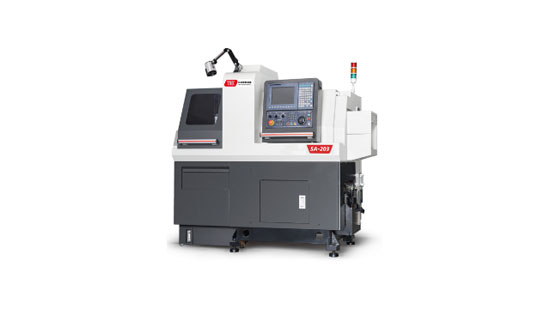

VIII. cnc turning milling center
- Modern turn-mill compound machining centers integrate both technologies, allowing turning and milling operations to be performed on a single machine. This significantly improves the machining efficiency and precision of complex parts while reducing the number of setups. However, understanding the fundamental principles of each technology remains essential.
- Turn-mill compound machining (Turn-Mill Compound Machining) combines the core functions of turning and milling, enabling synergistic machining of “rotating workpiece + rotating tool” on the same equipment. It perfectly integrates the advantages of both.
- The core logic is: using the efficiency of turning to handle rotationally symmetric features, leveraging the flexibility of milling to process complex contours, and eliminating multi-process errors through “single-setup machining.”
Below is a detailed analysis of the specific integration methods and advantages:
- Turn-mill compound machine tools are typically upgraded from CNC lathe platforms by adding a powered tool turret, C-axis (workpiece indexing function), and milling spindle, achieving the compound machining capability of “turning + milling.” Key hardware support includes:
- Powered Tool Turret: Mounts both turning tools (for turning outer diameters/faces) and milling tools (for milling slots/holes/contours), supporting independently rotating milling power heads.
- C-Axis Function: Allows the workpiece to be indexed (e.g., 1° per revolution) on top of turning, enabling circumferential milling or helical interpolation with the milling tool.
- Multi-Axis Linkage: The X/Z axes of turning are linked with the A/C axes (rotary axes) of milling to machine complex surfaces or irregular features.
- Traditional Mode: To machine a shaft with outer diameters, faces, keyways, threads, and holes, the process typically involves:
- Lathe (turn outer diameter → turn face → thread turning) → Milling machine (mill keyway → drill holes) → Drill press (tap threads), requiring at least 3–4 setups.
- Turn-Mill Compound Mode:After a single setup, the workpiece is sequentially machined through:
Turn outer diameter → turn face → thread turning → powered tool milling keyway → powered tool drilling → powered tool tapping.
- Advantages:Avoids positioning errors caused by multiple setups (traditional setup error accumulation can reach 0.02–0.05 mm, while turn-mill compound controls it within 0.01 mm), making it especially suitable for high-precision parts (e.g., aerospace shafts, medical implants).
- For rotationally symmetric features like outer diameters, faces, and threads, turning’s continuous cutting efficiency far exceeds milling (turning feed rates can reach 0.2–0.5 mm/rev, while milling typically ranges 0.05–0.2 mm/tooth). Turn-mill compound retains the batch-processing efficiency of turning.
- For asymmetric features (e.g., keyways, polygonal contours, angled holes, curved surfaces), the milling function of the powered tool turret can directly machine them without additional equipment. Examples:
- After turning an outer diameter, use a milling tool to mill a 30° angled slot relative to the axis.
- While turning a face, simultaneously use a milling tool to machine a center hole or chamfer.
- Utilize C-axis indexing to mill six evenly spaced threaded holes around a circle (replacing traditional drill press indexing).
- Time Cost: Reduces setup, handling, and alignment time (setup accounts for ~30% in traditional modes, reduced to 5% in turn-mill compound).
- Equipment Cost: A single turn-mill compound machine replaces multiple machines (lathe + milling machine + drill press), saving space and maintenance costs.
- Labor Cost: Reduces the number of operators (traditional setups require 2–3 workers for multiple machines, while turn-mill compound needs only one).
- Shaft-type parts with complex features: e.g., transmission shafts with keyways, threads, helical grooves, or flat markings.
- Disc-type parts: e.g., flanges (requiring face turning + bolt hole milling + center hole drilling).
- Small irregular parts: e.g., medical orthopedic implants (requiring outer contour turning + bone-contact surface milling).
- High-precision batch parts: e.g., automotive transmission gear shafts (requiring outer diameter turning + slot milling + tapping + inspection).
Summary: The Essence of Turn-Mill Compound Machining
- Turn-mill compound machining integrates the core advantages of both technologies (the efficiency of turning and the flexibility of milling) by adopting the model of “turning for the rotational body + milling for localized complex features.”
- Simultaneously, it resolves the contradiction between precision and efficiency in traditional multi-process machining through “single-setup machining.” It represents a typical advancement in modern CNC machining toward higher precision, efficiency, and flexibility.
- If you need specific case studies (e.g., programming concepts for turn-mill compound machining of a particular part) or equipment selection advice, feel free to discuss further.
👉 Thank you for reading!
👉 Taike As a swiss lathe manufacturers with 20 years of experience, we specialize in providing precision machining solutions.
👉 For your metal parts requiring machining evaluation, we offer:
✅ Free machining proposals
✅ Machining time estimation
✅ Prototype testing support
👉 Learn about our full range of CNC lathes and Swiss-type lathes now!
👉 Welcome to contact us!
